Welcome to the offical website of Atekon Automation Technology Co.,Ltd


Solutions
The Application of NA400 PLC in Thermal power plant auxiliary control system
- Categories:Thermal power industry
- Author:
- Origin:
- Time of issue:2020-03-27 16:14
- Views:
(Summary description)

The Application of NA400 PLC in Thermal power plant auxiliary control system
(Summary description)
- Categories:Thermal power industry
- Author:
- Origin:
- Time of issue:2020-03-27 16:14
- Views:
The auxiliary system of the thermal power plant is an important part of the thermal power plant and a key component of the operation of the power plant. It mainly includes the coal transportation system, ash removal/slag removal system, chemical water treatment system, etc., referred to as "coal ash water". In order to improve the control level, control method, safety and economics of the auxiliary system of the whole plant, realize the unattended on-site auxiliary workshop, improve labor productivity and automation level of the whole plant, the auxiliary system of the power plant generally implements the whole plant Centralized monitoring and establishment of public and auxiliary networks laid a good foundation for the realization of plant-wide plant monitoring (SIS).

1. Introduction
Thermal power plant auxiliary system is an important component of thermal power plant, and it is a key component part of plant operation, which includes coal handling system, ash / slag removal system, chemical water treatment system, referred to as "coal, ash and water." In order to improve the control level and control mode of whole plant’s auxiliary system and also safety and economy of system operation, and achieve local unattended operation in auxiliary workshop, improve labor productivity and automation level of whole plant, power plant auxiliary system ordinarily implement whole plant centralized monitoring, and establish public auxiliary network to lay a good foundation for whole plant monitoring (SIS).
2. System brief introduction
The entire Thermal power plant auxiliary control system consist of three subsystems: water treatment control system, ash/slag removal control system, coal handling programmed control system.
2.1 Water treatment control system
This system is mainly used in control and monitoring of boiler feed water, condensed water, recycled water, industrial waste water and drainage systems in thermal power plant.
Industrial water treatment system adopts local unattended operation mode, install PLC host cabinet in the control room of boiler feed water, and install remote station in industrial waste water workshop. Control system is accessed to water system control network through redundant bi-directional communication interface to achieve functional monitoring of data acquisition, program start/stop, interruption control (automatic step sequence control and semi-automatic step sequence control and hop step etc.) and individual equipment operation for fire-pump room (including tanks), drainage pump room, industrial waste water, sanitary sewage and other program-controlled systems through whole plant water system operation station. When operation condition of process system is abnormal, the system will give out alarm and emergency incident handling and interlocking protection.
Control devices of industrial water treatment system include putting into operation, stop, automatic and semi-automatic start and another set of standby unit program of process system program control. For sequential control, set step by step operation, group operation, independent operation, hop step, interruption and other operation functions, and also set program procedure time, status indication, display of fault reasons and other necessary choice and interlocking protection.
Program-controlled or manual dosing
Oily waste water treatment system may start or stop automatically against liquid level in oily waste water collection tank.
Sludge conveying and dehydration system can automatically start or stop against liquid level in mud pool. The equipment includes mud pool, mud conveying pump and dehydrator.
Pumps are linked and locked mutually between each other, and linked and locked with acid storage tank as well, stop pumps at low liquid level.
Start of feed pump is controlled against liquid level, start at high liquid level, stop at low liquid level.
Pumps switching (operation time added up)
Fans switching (operation time added up)
Protection and control of water pumps at low liquid level
Equipment failure alarm
Control system mainly includes data acquisition and sequential control functions. LCD screen can display technological process and measured parameters, operation display, operation status of controlled objects and group parameters. Off-limit alarm of parameters, fault of controlled objects or change of status can be displayed in current screenshots automatically in different colors with audio prompts. LCD screenshots can conduct recording of regular printing of monitoring signals, recording of off-limit alarm of parameters and recording of equipment operation. Through PLC to conduct program control and remote manual operation for the whole system, the PLC is built-in with necessary protection and interlock.
2.2 Ash/slag removal control system
Against working mode, ash/slag removal control system is divided into water flushing ash and pneumatic ash removal.
Functions of ash removal control system:
- Centralized monitoring and alarm function
- Audio alarm function
- Management report function
- Function of interface with plant level management information system
- System security management function
- Equipment management function
Ash removal control system conducts data acquisition and system control. Ash removal control system can conduct centralized monitoring, management and automatic sequential control for the operation, start, stop and fault of pneumatic ash removal conveying system, ash silo, ash removal air compressor system and gasification fan room of the whole boiler, and remote manual operation is also achievable.
Ash removal control system adopts LCD operation station as operator’s human-machine interface station, monitor and control the whole system through LCD screen and mouse, and no longer set conventional instrument panel desk and simulation screen. All operation parameters and alarm signals can be printed and recorded.
For those controlled objects such as pumps, fans and valves, monitoring can be conducted on operator’s station LCD screen in ash removal control room, and local control can also be done by control switch on MCC or the button on valve electric actuator, and for pneumatic valves, local control can be done by the button installed on the solenoid valve box (supplied with the process system); remote/local switching function can be achieved on MCC and solenoid valve box, and “in local control” signal can be output to the control system.
Ash removal control system adopts combined control modes of automatic program control, remote manual operation and local operation. Program control can be set with automatic operation, step operation, group operation or independent operation with functions of hop step, interruption and bypass etc., it can also be set with necessary step time, status indication, choice and interlock functions.
Auxiliary workshop operator’s station located in central control room can monitor technology process and operation status of relative systems through each auxiliary control system to achieve local unattended on duty. Auxiliary workshop central control network has redundant communication interface with DCS to achieve the monitoring of DCS on auxiliary workshop.
2.3 Coal conveying program control system
Functions of coal conveying control system:
- Start/stop function of system fixed program
- Start/stop function of system combined program
- Interlock start/stop function of one to one equipment
- Automatic coal blending function in raw coal warehouse
- Partial interlock relief control function
- Anti-seize and anti-jam function of tee joint baffle plate and electric push rod on coal plow
Coal conveying program control system can complete the control of coaling and coal blending when thermal power plant is under normal operation, monitoring operation status of coal conveying equipment and security interlock and protection, monitoring and control relative power sources of coal conveying system. Coal conveying program control system can communicate with auxiliary workshop’s control system so as to be able to monitor coal conveying system in master control room. The two systems are connected with 10/100M redundant industrial Ethernet, Coal conveying program control manufacturer provides redundant optical fiber communication interface and relevant information including software needed by communication. Coal conveying system can be interlocked and communicated with coal conveying broadcasting call system and coal conveying closed circuit industrial television system. On upper computer, the system can control start/stop of coal conveying system’s main equipment, set with start forecast system, fault sound-light alarm system with functions of fault indication and lamp inspection. The system can display operation status of belts and retractable belts, status indication of coal breaker and coal screen, fault position and nature, high-low coal level in coal warehouse.
Coal control functions of the system are divided into three modes: automatic, manual and local.
Coal blending control function is divided into program control and manual.
The system has thorough accident alarm function. When an accident occurs, the voice alarm system will give out voice signal, and meanwhile, CRT screen will display flow chart of fault area, and the color of accident equipment graph will be changed, fault nature and time of occurrence will be displayed on the above of the screen. Fault alarm system has the functions of voice alarm, real-time alarm query, historical alarm query and alarm printing.
Management monitoring function refers to the whole coal conveying system having computer management function, which can automatically collect operation condition and relevant data, can achieve formation and modification of real-time flow, status display with tabulation function, can print various reports as per schedule time or call, can inquire and call relevant data on CRT. Reports have the functions of equipment operating time recording, historical query of operating time, coal quantity statistics and flow recording etc.
3. Solution
Through analysis and research on the above-mentioned auxiliary system, based on the principles of cost performance, stability and functional maturation, we design the following system solution, system network structure is as follows:

Figure 1 Network structure diagram of auxiliary control system of thermal power plant
- System structure
The system adopts NA400 PLC as control station, including water treatment control system, ash/slag removal control system and coal conveying program control system. Each control station is allocated with two Ethernet switchboards, to form a redundant ring network with the two industrial Ethernet switchboards of backbone network. There are engineer station and operator station in each control station, there are engineer station, operator station and redundant server in central control room.
- Control system
Central processor of NA400 adopts IntelTM PentuimM chips, integrated with two Ethernet TCP/IP communication interfaces, no need communication module, which is cost saving and convenient for networking. Modular structure is easy for installation and replacement, modules can be installed on rack’s any positions. Rack extension does not need extension module, I/O extension can be achieved through a bus cable.
Complete intelligent I/O design and a series of security and reliable design provide a guarantee of safe and reliable operation of the system. NA400 PLC adopts fieldbus network, it not only has the characteristics of fast communication rate, strong anti-jamming capability, low cost, simple structure and good real-time, but also has good expansibility, which is easy to achieve flexible configuration of modules and greatly improve adaptability to environment and installation requirements. Integrated with all five programming languages of IEC61131-3 and original sequential control diagram language and all languages can be mutually called between programs, which makes programming much more flexible and convenient and can meet the requirements of multiple complex working conditions. Ethernet interface provided can achieve remote programming and debugging for remote control center to modify control flow of on-site control device and make online maintenance.
- Network structure
The whole auxiliary control network adopts modular industrial switches, where backbone switch is redundant. Adopt multi-mode optical cable and industrial grade switches to form industrial Ethernet ring network, adopt uniform network platform and software platform to interconnect various different auxiliary control systems and to achieve relevant centralized control of peripheral auxiliary control system. The whole auxiliary control system adopts star-ring hybrid structure and various auxiliary control systems are connected by Ethernet ring network and are divided into backbone network and subring networks. Each auxiliary control system adopts star way to connect with the backbone network, the backbone network adopts super redundant ring technology, when any point on the ring network breaks down, the system can restore normal operation within less than 500ms time, and the allocated redundant switch can achieve multi-point fault tolerance function of the whole network.
Thus, the entire auxiliary control network not only has the characteristics of fast switching, safety and reliability of ring network, but also integrates the capabilities of multi-channel, convenient construction and flexible expansion of star network so that the reliability and instantaneity of the system is improved.
- System functions
Adopting configuration software to achieve the following main functions:
1) Graphical display: Maintain consistency with each subsystem’s operation interface and display technological process of each subsystem;
2) Real-time dynamic display: Provide measuring point real-time value and status required by the monitoring of production operation;
3) Trends: Provide real-time/historical trends display and printing functions;
4) Alarm: With functions of pop-up screen real-time alarm, voice alarm, alarm acknowledgment, alarm printing and alarm historical recording;
5) Functions of operation recording and events recording: Record as per time sequence real-time alarm information, alarm history and application program running list after start of the system, which is convenient for operation personnel to query and analyse;
6) Fast switching of the screens of each auxiliary subsystem;
7) Uniform system login screen, different security levels and operating authorization to ensure stable operation of the system.
The main interface of the auxiliary control system of the thermal power plant is shown below:
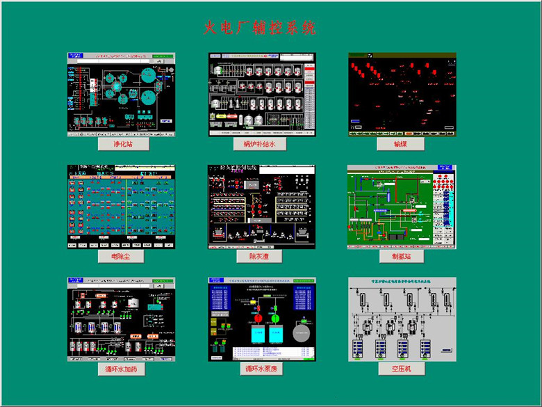
Figure 2 Main interface of auxiliary control system of thermal power plant
Scan the QR code to read on your phone
底部二维码

Welcome to Atekon
Technology official Wechat
底部联系方式
Address: Floor8,BuildingD,Cloud Security City,No.19 Ning shuang Road,Yuhuatai District,Nanjing
Production Center: No. 219 Qingshuiting West Road, Jiangning District, Nanjing City
Telephone: 025-68530188 (Switchboard)
Fax: 025-68530178
Service Hotline: 400-025-0150
Technical support: 025-68530179
底部备案号
Atekon Technology Co.,Ltd Record number: 苏ICP备09042342号-1